
The ability to accurately diagnose sensor malfunctions can save time and money and increase customer confidence. Modern fleet teams and workshops frequently combine live diagnostic information (DTCs, freeze frames, Live parameters) with Electronic Parts Catalogues (EPCs) and OEM technical data to quickly move from a sign of trouble to an exact repair or component.
This article explains the practical workflow for Diagnosing Sensor Failures via EPC Data, the best methods, and the tools for effectively diagnosing sensor-related problems.
Why should you combine EPC Data with Diagnostic Codes?
Diagnostic Trouble Codes (DTCs) indicate the location where the vehicle’s control units identified a problem; however, they do not guarantee the failure of a physical component. EPCs provide vehicle-specific lists of parts, location diagrams, and part numbers, transforming a generic error message into a specific parts and repair plan. Utilising both can reduce the need for return visits, parts swaps and repeated visits.
A Typical Workflow: From fault code to repaired sensor
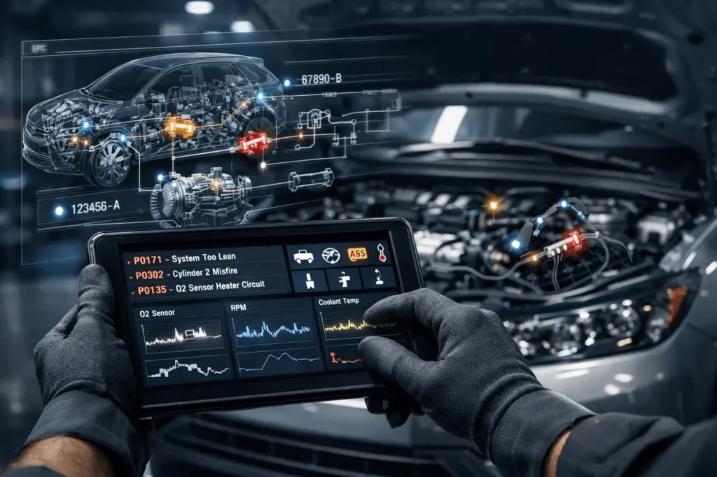
- Capture the fault and contextual data. Plug in a dependable scan tool (OBD-II, J1939, or OEM-level) and read stored or active DTCs, frozen-frame data, and real-time data (sensor values, short-term fuel trim, voltages). Live and freeze-frame parameters typically indicate whether the problem was caused by a transient (shorted connection) or a long-lasting sensor reading.
- Determine the vehicle’s specific identification (VIN or engine code). The majority of EPC systems are VIN-sensitive. You must enter this VIN in the EPC so that the parts list and wiring diagrams match the exact variant of your vehicle. This will prevent you from purchasing visually identical but not compatible sensors.
- Locate DTC in Potential Parts and Locations in the EPC, use the EPC’s “search by fault code” or symptom index if it is available. It will show the affected system, pertinent parts, and the subassemblies. When the EPC supports fault-code searches, it usually links to diagrams, connector pinouts, and harness routing. If EPC entries are unclear, you can cross-reference them with the workshop’s OEM manuals.
- Make sure to conduct a few simple electrical checks before replacing parts. Examine the connectors and wiring for corrosion, test the reference voltages and sensor outputs with a scope or multimeter, and compare live sensor data with anticipated intervals. The majority of “failed sensor failures” are caused by grounding, wiring or harness problems. Technical bulletins issued by OEMs (found alongside EPC information or in workshop manuals) frequently list common “false-fail” symptoms.
- Replace only if evidence supports it: Replace the sensor when you have confirmed that it is out of specification during testing or during an OEM-guided bench/functional check. If replacing, use the OEM part numbers listed in the EPC and note the required calibration or coding procedures in the instruction manual.
- Verify Repair using a Road Test or a Post-Repair scan. Clear any codes, run the same scenario, and observe for live and frozen frames. If the code comes back, you need to re-evaluate your wiring, the control module’s behaviour, or software issues.
Diagnosing Sensor Failures via EPC Data: Sources of data and software that are important
- Electronic PC systems (OEM or dealer-level ) and multi-brand EPCs that are aftermarket) VIN-specific lists of parts as well as exploded views and location diagrams. Make use of the EPC fault-code lookup when you can.
- Workshop manuals for manufacturers’ tests, test procedures, anticipated sensor resistances, calibration procedures and other tools.
- Advanced diagnostic tools (Jaltest Snap-on, Jaltest dealer tools) analyse modules above the engine (ABS, BCM, TCU), view freeze-frames, and perform guided tests.
- The Oscilloscope and bench-test fixtures are vital for confirming the integrity of signals and the PWM sensor.
- Telematics and fleet platforms can provide historical DTC trends and remote freeze-frames to address frequent sensor failures in fleets.
Diagnosing Sensor Failures via EPC Data: Common Traps and ways to stay clear
- If you think the DTC means a sensor is bad. DTCs often indicate a problem with the circuit or an out-of-range reading caused by contamination, poor grounding, or ECM issues. Always check the wiring and power first.
- Making use of faulty or second-hand components without verifying the correct fit or coding requirements. VIN-based EPC search prevents the use of incompatible sensors and flags whenever adaptation or coding is required.
- Do not pay attention to upgrades or software. Specific sensor behaviour can be correctable by software module updates. Check OEM service bulletins before replacing parts.
Advanced Techniques: Analytics and Predictive Maintenance
Advanced shops and fleet operators use EPC-derived inventories and telematics to identify likely sensor failures (based on recurring fault patterns, including mileage, as well as environmental conditions). This allows proactive stocking of OEM sensors and scheduling maintenance windows to replace parts before they fail. Data-driven strategies can reduce downtime and increase first-time fix rates.
Diagnosing Sensor Failures via EPC Data: Practical Checklist to Help Technicians
- Read and save all DTCs, including freeze-frames, DTCs, and real-time values.
- Enter the VIN in EPC and search for related part numbers and diagrams.
- Examine wiring and connectors both electrically and visually.
- Test sensor against OEM specifications (multimeter/Oscilloscope).
- Refer to OEM service bulletins for information on known problems or software fixes.
- Replace only if tests reveal a sensor fault. Use the OEM part that is EPC-approved.
- Clean Codes, carry out modifications/coding if needed and confirm with the road tests.
Final Thoughts
EPC data helps bridge gaps between diagnosis codes and effective repairs. When combined with disciplined testing of electrical power, OEM protocols, and the latest Diagnostic tools and software, the EPC-driven workflow can reduce unnecessary parts replacement and increase repair accuracy. For Repair and fleet managers’ shops, combining telematics-driven trends and EPC-sourced parts scheduling is a practical step towards effective, predictive maintenance.
Frequently Asked Questions (FAQs)
1. Can I assign a DTC straight to a piece with EPC?
But not always. EPCs frequently list possible parts and locations that could trigger the DTC; however, root-cause verification remains a requirement for electrical testing, and references to OEM procedures are required. Use EPC guidance plus live-data checks.
2. How do I reduce wrong-fit parts caused by VIN errors?
OEM dealer tools, as well as advanced aftermarket products (Snap-on, Jaltest, Autel, and others), provide in-depth access to modules, as well as freeze-frame and guided tests that work with EPC workflows.
3. We get outdated parts after monthly imports. How can we detect missing updates?
Significantly, sensors may be affected by the engine, emission specification code, connector, or the engine itself. VIN-based EPC lookups ensure compatibility and eliminate returns.
4. Should we build our own EPC search or buy a vendor solution?
Suppose multiple sensors on the same circuit show abnormal readings, or live data fluctuates with vibration/temperature, suspect wiring, grounds, or the ECU. Utilise scope traces along with wiring layouts from EPC to identify.
5. How can UX improvements reduce parts-order errors?
Yes. Telematics can capture event-driven DTCs, freeze-frame snapshots, and historic trends, which help diagnose intermittent or environment-triggered failures.
Also Read –
VIN Lookup in EPC: The Smart Way to Identify the Right Vehicle Parts
How EPC Model Year Updates Improve Accuracy & Parts Management